
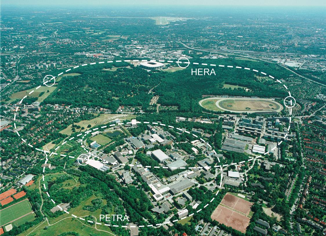
The ZEUS Experiment was a high energy particle physics experiment based on the HERA colider at the DESY laboratory in Hamburg, Germany.
 The HERA
machine was situated in a 5 m diameter tunnel, 10-25 m
underground, with a circumference of approximately 6.3 km. It
extended beyond the boundaries of the DESY laboratory and ran
underneath the Hamburg Volkspark. The renovated PETRA
accelerator (see TASSO) was used as
an injector for HERA. HERA was an electron-proton collider,
colliding 30 GeV electrons with 820 GeV protons for a centre of
mass energy around 314 GeV. It could also collide positrons and
protons.
The HERA
machine was situated in a 5 m diameter tunnel, 10-25 m
underground, with a circumference of approximately 6.3 km. It
extended beyond the boundaries of the DESY laboratory and ran
underneath the Hamburg Volkspark. The renovated PETRA
accelerator (see TASSO) was used as
an injector for HERA. HERA was an electron-proton collider,
colliding 30 GeV electrons with 820 GeV protons for a centre of
mass energy around 314 GeV. It could also collide positrons and
protons.
The ZEUS detector, shown schematically in the upper left, was a general purpose 4π detector. Protons entered the detector along the beampipe from the right; electrons from the left; and collided in the central region. Charged particle produced by the interactions were tracked in the vertex and central tracking detectors (light blue) which sat inside a 1.4 T solenoidal magnetic field. This enabled the tracking to also momentum analyse the particles. Beyond the tracking detectors were the barrel, forward, and rear high precision, depleted uranium calorimeters (red) which measured the energies of the particles or jets of particles produced. Beyond these detectors was the iron yoke which was instrumented with muon chambers to track muons which passed through the other detectors. Also in the forward (left) direction there was a special muon detector system incorporated in a toroidal magnet. Other small angle detectors and luminosity monitors are not shown in this view as they are situated away from the main detector.
At the high energies accessible with HERA (Q2~100,000 GeV2) it was not so much an electron-proton collider as an electron-quark collider. Momentum transfers of this magnitude correspond to probing the struture of the proton at a scale down to 0.0007 fm and considering the proton radius is on the order of 0.8 fm this means we were looking deep inside the proton. Of course not all interactions were at such a high Q2 so the data from HERA probed the proton over a range of distances and allowed the structure to be studied at many scales.
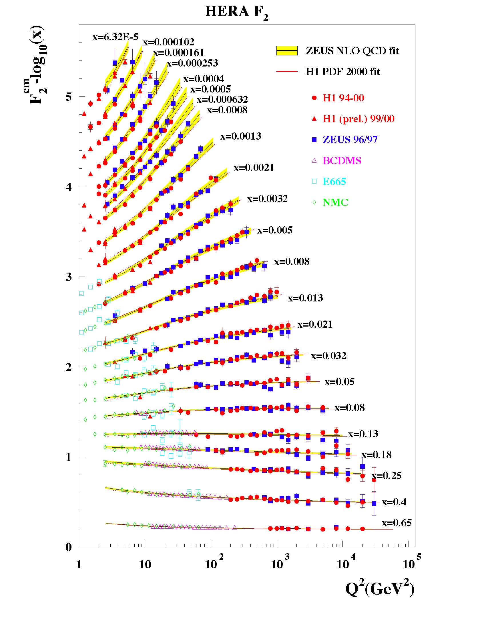 The plot at right shows the F2 structure
function of the proton as a function of Q2 for
different values of x, the Bjorken scaling variable. The
data includes measurements from fixed target experiments as well
as the HERA results. The measurements are impressive as they
span four orders of magnitude in both x and
Q2. The variable x can be interpreted
as the fraction of the proton momentum carried by the struck
parton. At high x values the structure function does not
vary with Q2; a property known as Bjorken
scaling. But as x decreases below ~0.1 this scaling fails,
or is violated, and the structure function rises with
Q2. The great success of quantum
chromodynamics is that this behavior is expected and can be
calculated (using DGLAP evolution) given the structure function
at some low Q2 value usually around 4
GeV2. At high x (x>0.1) the scattering
is from a valence quark and is independent of momentum transfer.
But as smaller x regions are studied the contribution
from the gluons and sea quarks increase and these contributions
are not constant but increase as you resolve smaller and smaller
scales with increeasing momentum transfer.
The plot at right shows the F2 structure
function of the proton as a function of Q2 for
different values of x, the Bjorken scaling variable. The
data includes measurements from fixed target experiments as well
as the HERA results. The measurements are impressive as they
span four orders of magnitude in both x and
Q2. The variable x can be interpreted
as the fraction of the proton momentum carried by the struck
parton. At high x values the structure function does not
vary with Q2; a property known as Bjorken
scaling. But as x decreases below ~0.1 this scaling fails,
or is violated, and the structure function rises with
Q2. The great success of quantum
chromodynamics is that this behavior is expected and can be
calculated (using DGLAP evolution) given the structure function
at some low Q2 value usually around 4
GeV2. At high x (x>0.1) the scattering
is from a valence quark and is independent of momentum transfer.
But as smaller x regions are studied the contribution
from the gluons and sea quarks increase and these contributions
are not constant but increase as you resolve smaller and smaller
scales with increeasing momentum transfer.
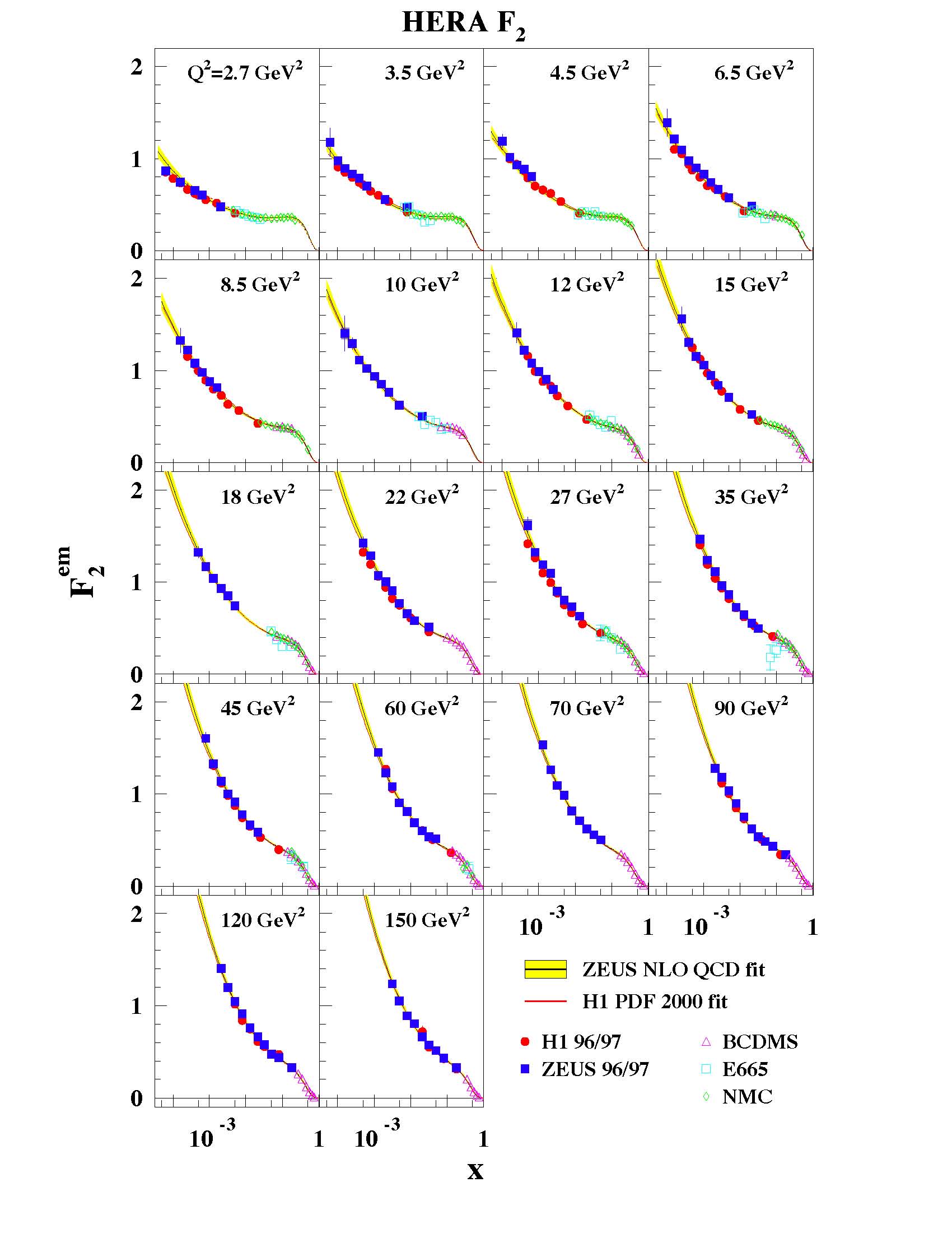 The
increasing effect of the gluons and sea quarks with
Q2 is evident when we look at the structure
function as a function of x for different
Q2 values. At low Q2 the
increase is gradual as x decreases but at higher
Q2 the rise becomes steeper and steeper
indicating the increasing importance of sea and gluon
distributions.
The
increasing effect of the gluons and sea quarks with
Q2 is evident when we look at the structure
function as a function of x for different
Q2 values. At low Q2 the
increase is gradual as x decreases but at higher
Q2 the rise becomes steeper and steeper
indicating the increasing importance of sea and gluon
distributions.
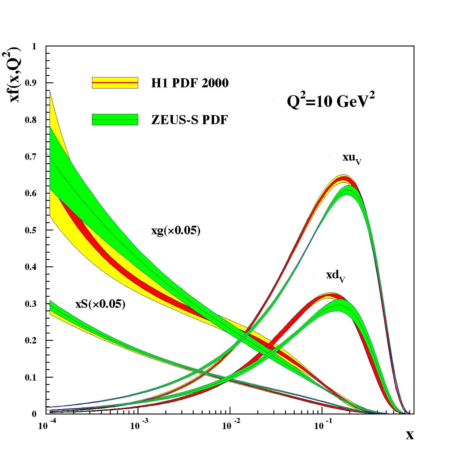 All of this data can
be analysed to determine the distribution of quarks and gluons
in the proton. The bands at right show fits to the data by the
ZEUS and H1 collaborations at HERA to extract the parton
distributions. At higher x values the valence u
and d quarks dominate. But as x decreases the sea
and gluon contributions quickly become the most important
contribution. Note that the sea and gluon distributions are
divided by a factor of 20 to fit on the graph!
All of this data can
be analysed to determine the distribution of quarks and gluons
in the proton. The bands at right show fits to the data by the
ZEUS and H1 collaborations at HERA to extract the parton
distributions. At higher x values the valence u
and d quarks dominate. But as x decreases the sea
and gluon contributions quickly become the most important
contribution. Note that the sea and gluon distributions are
divided by a factor of 20 to fit on the graph!
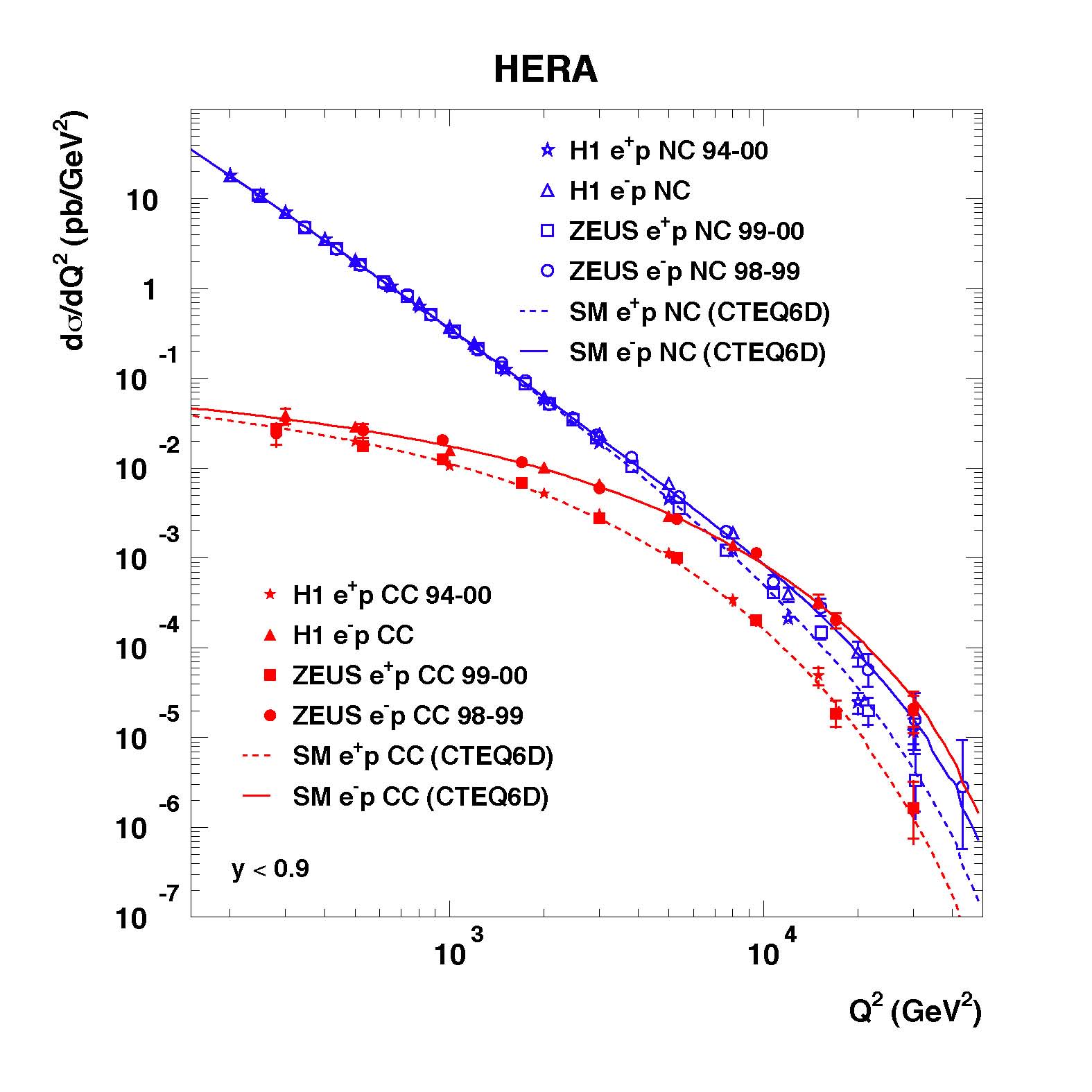 Another result to
come from the HERA experiments was the measurements of the
neutral and charge current cross sections. The electro-weak
interaction is mediated, to first order, by the exchange of
photons (the carrier of the electromagnetic interaction) or by
exchange of W or Z bosons (the carriers of the
weak interaction). Exchange of either photons or Z bosons
transfer no charge and are called neutral currents. The W
bosons however are charged and these interactions are called
charge currents. At low momentum transfers,
Q2, the neutral current cross section is much
larger as the charge current cross section is suppressed by the
mass of the W boson (80 GeV/c2). As the
momentum transfer approached the 802 or 6400
(GeV/c2)2 then the two cross sections
become comparable in magnitude.
Another result to
come from the HERA experiments was the measurements of the
neutral and charge current cross sections. The electro-weak
interaction is mediated, to first order, by the exchange of
photons (the carrier of the electromagnetic interaction) or by
exchange of W or Z bosons (the carriers of the
weak interaction). Exchange of either photons or Z bosons
transfer no charge and are called neutral currents. The W
bosons however are charged and these interactions are called
charge currents. At low momentum transfers,
Q2, the neutral current cross section is much
larger as the charge current cross section is suppressed by the
mass of the W boson (80 GeV/c2). As the
momentum transfer approached the 802 or 6400
(GeV/c2)2 then the two cross sections
become comparable in magnitude.
In addition to colliding electrons and protons HERA can also accelerate positrons and collide these with protons. This allows both charges of W bosons to be exchanged, negative for electron scattering and positive for positron scattering. Once again QCD accurately predicts the cross sections.
A great deal of my professional career was spent on the ZEUS experiment. First from 1983 to 1986 as a post-doc at the Rutherford Appleton Laboratory, RAL, near Oxford I worked on the R&D for the central tracking detector, CTD, for ZEUS. This involved testing different drift cell designs, gas mixtures, operation in magnetic fieldm readout schemes, etc. The tests were done in a test beam facility at DESY and were carried out by myself and three or four technicians. In the end the we arrived at the final design for the CTD and built a quarter section of a full size prototype. The actual detector was built after I left RAL but the design of 8 sense wire drift cells with a 45 degree tilt with repect to the radial line, and 9 superlayers was from the design we finalised.
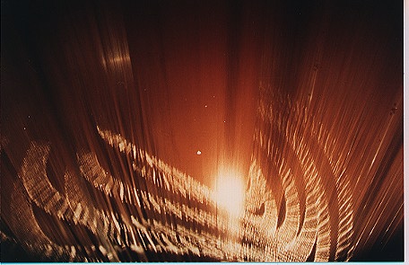 A view of the inside of
the finished central tracking detector for ZEUS is shown at
right. The final chamber is 2.4 m long and 1.65 m in diameter.
It consists of 24,192 wires with 4,608 sense wires used for
readout. Five of the superlayers are axial with the remaining
four layers at a slight stereo angle so that tracking can
reconstruct the axial position of the track as well as the
radial and azimuthal position. The readout also allows a axial
position to be determined by time difference from either end of
the chamber. In addition to position information the central
tracking detector measures the energy deposited by the particles
traversing the chamber which helps in particle
identification. Readout is via flash analogue to digital
converters (FADC's) with a pules finding algorithm to determine
timing and the charge integral.
A view of the inside of
the finished central tracking detector for ZEUS is shown at
right. The final chamber is 2.4 m long and 1.65 m in diameter.
It consists of 24,192 wires with 4,608 sense wires used for
readout. Five of the superlayers are axial with the remaining
four layers at a slight stereo angle so that tracking can
reconstruct the axial position of the track as well as the
radial and azimuthal position. The readout also allows a axial
position to be determined by time difference from either end of
the chamber. In addition to position information the central
tracking detector measures the energy deposited by the particles
traversing the chamber which helps in particle
identification. Readout is via flash analogue to digital
converters (FADC's) with a pules finding algorithm to determine
timing and the charge integral.
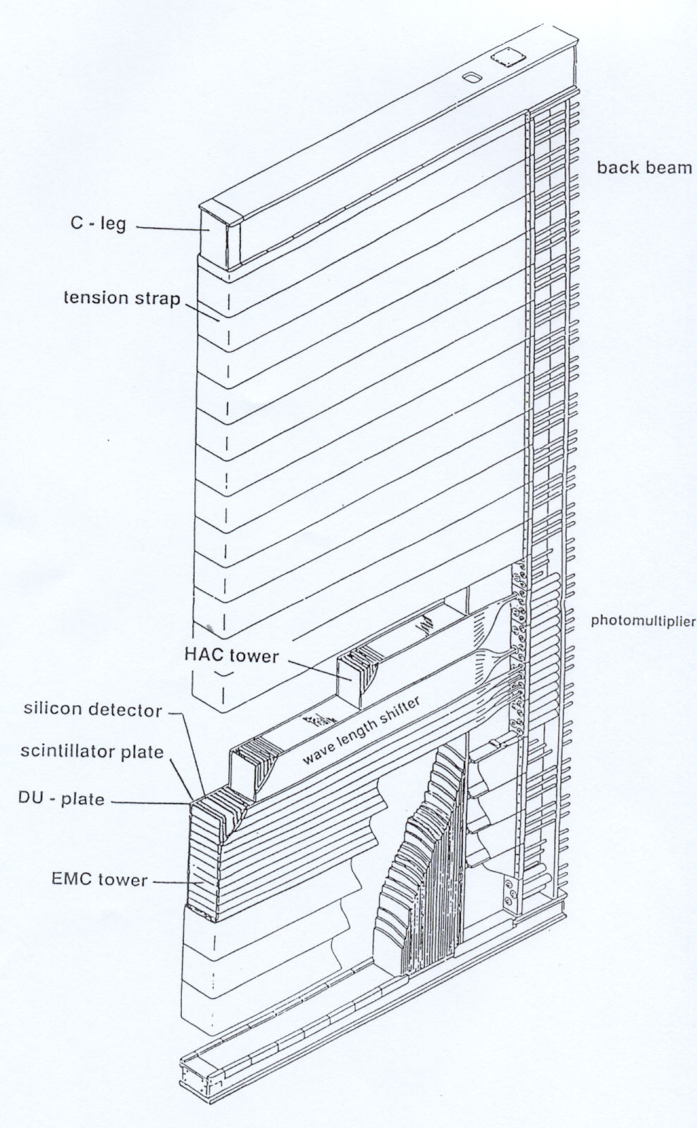 From 1986 to 1991 I was at
York University in Toronto where we worked on the design,
prototyping, and construction of the forward (F) and rear (R),
high precision, depleted uranium calorimeters (CAL) for the ZEUS
detector. A cut-away sketch of a single forward calorimeter
(FCAL) module is shown at left. The calorimeter modules are all
20 cm wide but vary in height and depth. The largest modules
(like the one shown) are 5 m high and 3 m deep and weigh 12
t. The smallest are only 5 t. In total there are 48 modules in
the ZEUS F/RCAL.
From 1986 to 1991 I was at
York University in Toronto where we worked on the design,
prototyping, and construction of the forward (F) and rear (R),
high precision, depleted uranium calorimeters (CAL) for the ZEUS
detector. A cut-away sketch of a single forward calorimeter
(FCAL) module is shown at left. The calorimeter modules are all
20 cm wide but vary in height and depth. The largest modules
(like the one shown) are 5 m high and 3 m deep and weigh 12
t. The smallest are only 5 t. In total there are 48 modules in
the ZEUS F/RCAL.
The ZEUS calorimeter is a sampling calorimeter which means it has alternating layers of active detector (scintillator) and dense absorbing layers (depleted uranium - DU). The absorber layers serve to slow down the high energy particles being studied and to convert their energy into radiation which is detected in the active layers. Thus some of the energy is lost in the absorber layers and the calorimeter only samples the total energy. However, with suitably thin layers this sampling is proportional to the total energy. The light produced in the scintillators is read out on both sides of the module by wavelength shifter (WLS) and light guides coupled to photomultiplier tubes (PMT's). The read out is segmented into towers of varying depth. The electromagnetic section (first 25 layers) has 5x20 cm2 towers followed by two hadronic sections (80 layers each) in 20x20 cm2. Reading the detector out in towers from both sides allowed a rough position measurement to be made. Readout in depth provided a good lepton identification technique.
The mechanical support for the module comprises of a steel T-beam at the back with upper and lower arms. The DU plates are clamped to the upper and lower arms but the main mechanism for holding the module together are the stainless steel straps whic extend over an aluminum front plate and back to the T-beam on both sides. These straps are each tensioned to a foce of 2 t. Tiny tungsten carbide spacers at the corners of each 20x20 cm2tower hold the DU plates in positionand prevent the force from bearing on the plastic scintillator.
There are a number of important parameters which have to be optimised in such a detector.
- The e/h ratio or ratio of responses to electromagnetic and hadronic processes should be as close to unity as possible. Because the calorimeter measures both leptons (electrons, positrons, photons) and hadrons (primarily pions) one wants the response to be the same. This is desireable both for simplicity in calibration but also because jets of particles contain varying contributions of electromagnetic and hadronic particles and thus the resolution is best when the response is independent of the fraction of one or the other. For a sampling calorimeter this ratio usually depends on the relative thicknesses of the absorber and active layers. For a depleted uranium - scintillator calorimeter we found through tests at CERN that the optimal thicknesses were 3.2 mm thick DU with 2.2 mm thick scintillator.
- Compensation is the ability of a calorimeter to account for the contribution of neutral particles like neutrons to the shower energy. Often the energy of neutral particles is not detected and thus the variation in the number of neutral particles in a jet leads to worse energy resolution. A depleted uranium - scintillator calorimeter provides compensation through fission and scattering the low energy neutrons from the protons in the scintillator whose energy is then detected.
A great many details were optimised for the ZEUS calorimeter.
- First the DU plates were completely enclosed in stainless steel. This contained the rust-like dust that forms on DU but also reduced the natural radiation from the uranium striking the scintillator. This had the benefit of reducing the background noise to acceptable levels but also provided a stable (because of the long half-life) energy signal for calibration. In the electromagnetic section the thickness was 0.2 mm while in the hadronic sections 0.4 mm was used to reduce the signal to comparable levels.
- The scintillator tiles were wrapped in white Tyvek paper with a pattern imprinted on it to ensure uniformity in light output regardless of postion.
- The wavelength shifter also had a background reflector with a pattern designed for uniform response regardless of depth in the calorimeter.
- Beyond the active region of each wavelength shift it was coupled to a clear light guide for optimal light transmission to the photomultiplier tubes.
- To reduce Cerenkov radiation for high energy particles traversing the wavelength shifter or light guides a UV filter was placed before each photomultiplier tube.
Finally a number of complimentary calibration techniques were also built into the detectors.
- Optical fibres were connected to each photomultiplier tube and coupled to a last light flasher system in the upper portion of the support structure. This enabled the timing and gain of the PMT's to be monitored.
- Hollow tubes ran beside each wavelength shifter bar and a Cobalt-60 source on a wire could be driven through the tube to measure the response of the WLS and scintillator at each depth.
- Most modules were also tested and calibrated in a test beam at CERN.
At York University we first worked on the mechanical design of the calorimeter to optimise the active area and performace of the calorimeter. Then four protype modules with full depth but only four towers each were built and shipped to CERN for testing. Once the basic design was proven we leased a light industrial site for construction of the real modules. The design was finalised and construction of the real modules began. In the end 26 of the 48 F/RCAL modules were built in Canada with the remainder built at NIKHEF in Amsterdam.
 Finally 1991-1998 as a DESY
physicist.
Finally 1991-1998 as a DESY
physicist.
The experiment started taking data in 1992 and was shut down in 2007.