Project Examples from Mechanology
Examples of my work while at Mechanology
During my time at Mechanology, I worked on the fabrication of a prototype compressor for use in an automobile fuel cell. My primary task was to model the various parts and assemblies in SolidWorks. Below are a few drawings of those models. Click on the thumbnails for a larger image.
-

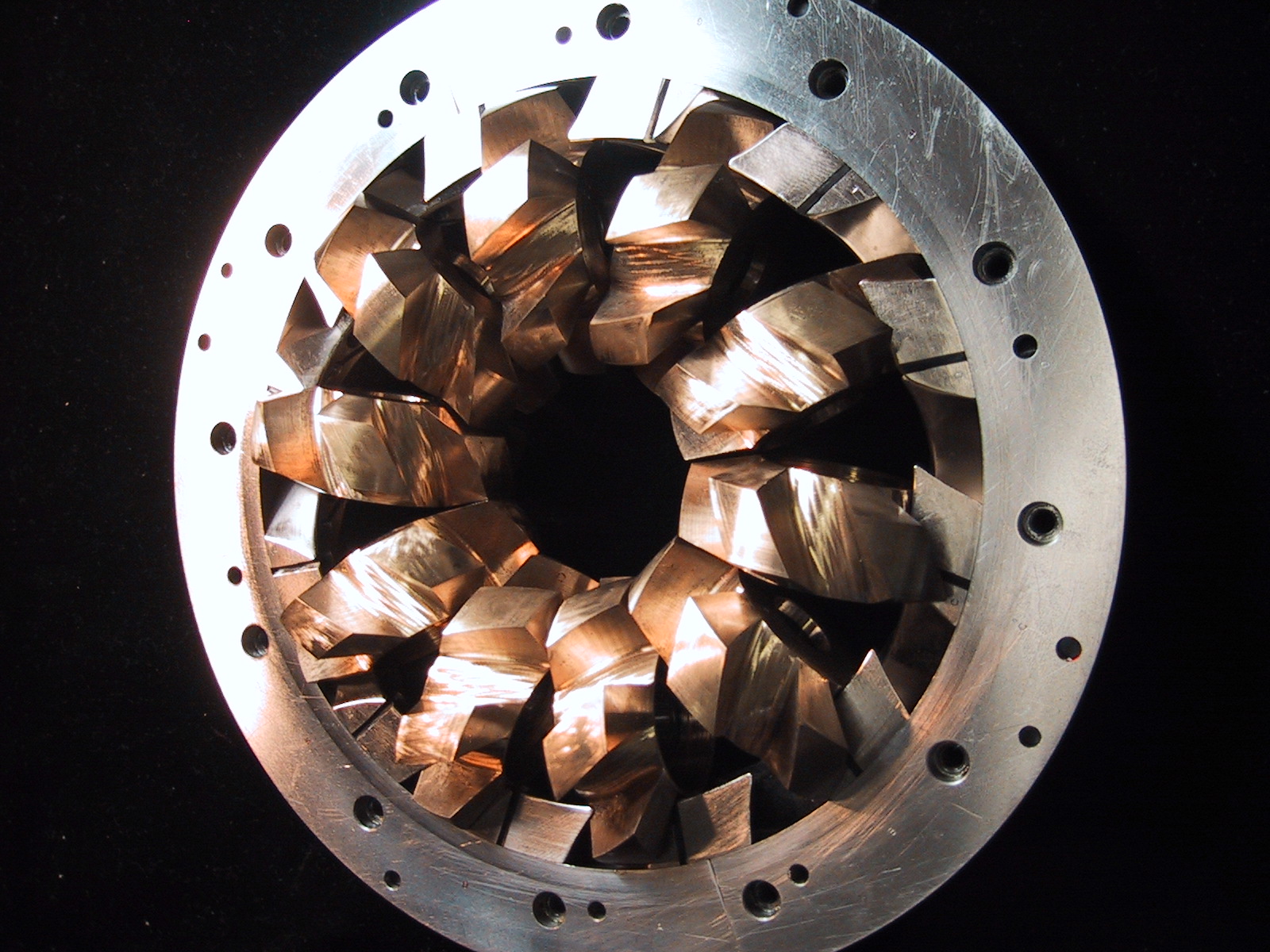
- This image shows the heart of the system. The rotation of the outer steel ring drives the rotation of each of the smaller bronze rotors. As the "teeth" of these rotors mesh and unmesh, they open and close a series of compartments between them; air is expanded as these compartments open, and compressed as they close. I did not design these parts myself, but I included the picture to give a better understanding of the project. And it does make a very nice image.
-
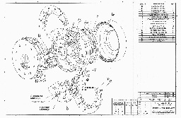
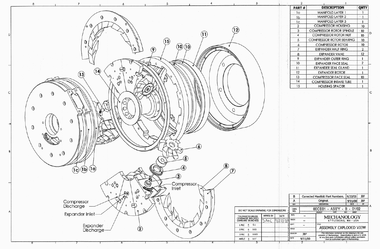
- This is an exploded view of the entire prototype compressor. I modeled each of these parts in SolidWorks. In addition, I got to designed the intake/exhaust Manifold myself (parts 1a-1c on the left end).
-
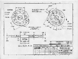
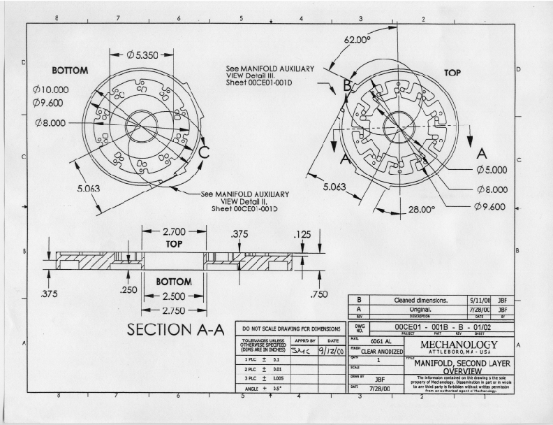
- Because the compressor used ten small rotors working in parallel to compress a larg volume of air, the manifold was needed to funnel air between a single source and each of the the compression and expansion chambers. For ease of construction, it was built in three parts. This is a drawing for the middle layer of the Manifold.
-
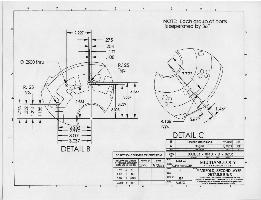
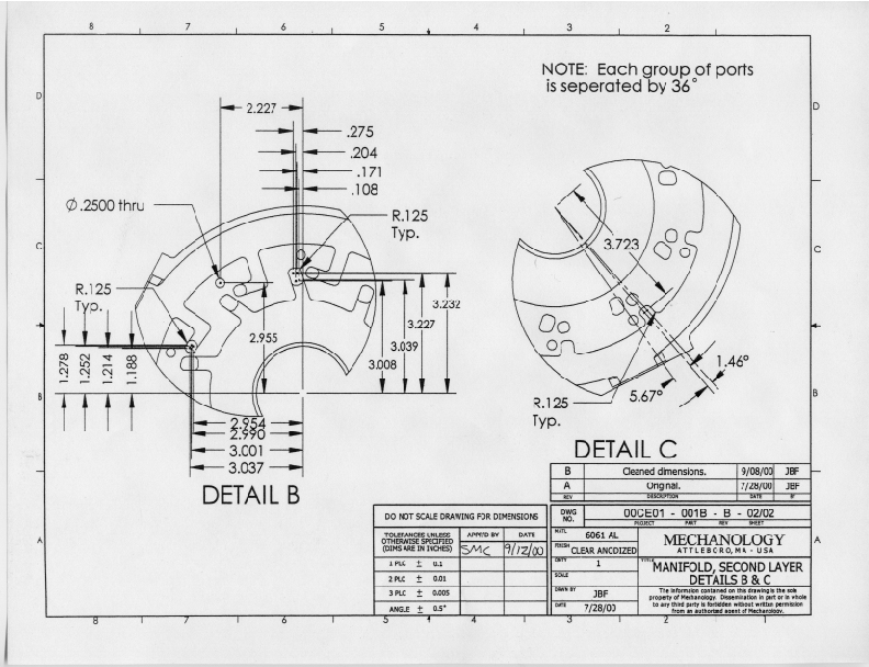
- This is the detail from the previous drawing.
-
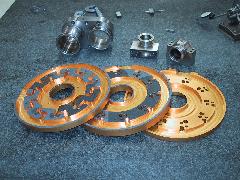
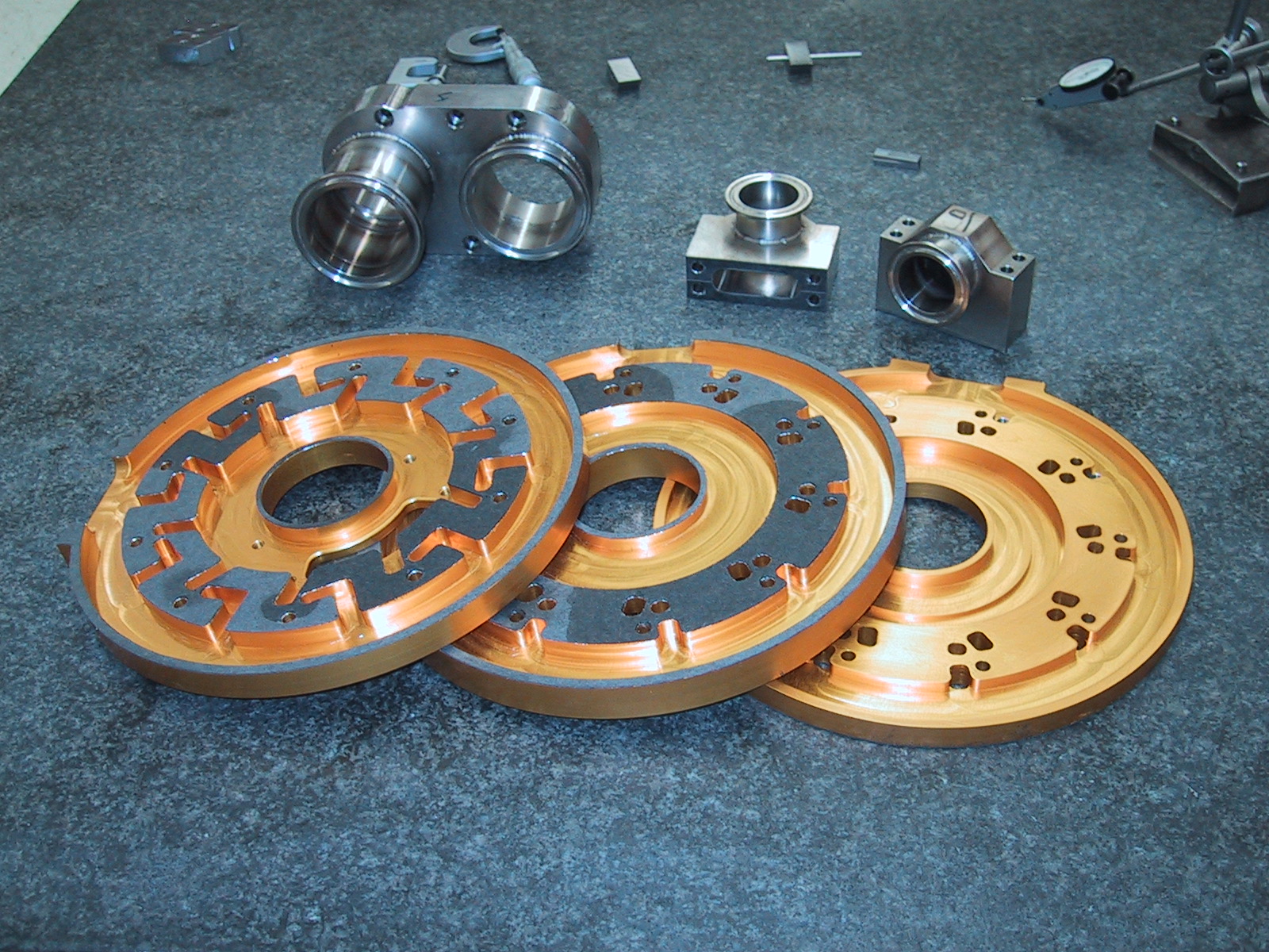
- This is a photograph of the actual prototype manifold. Each of the three sections are visible (the left most and middle layer have been flipped upside down to give a better view of the interior). The manifold contains three separate chambers inside it which funnel air to the Expander Inlets, and from the Compressor and Expander Discharges. The hole in the center of the manifolds provides air to the compressors.
-
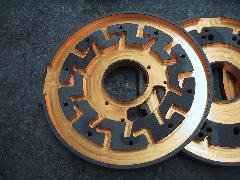
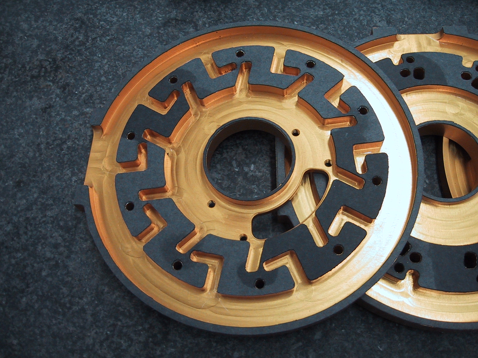
- This is a closer view of the interior of the manifold's top layer.
-
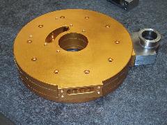
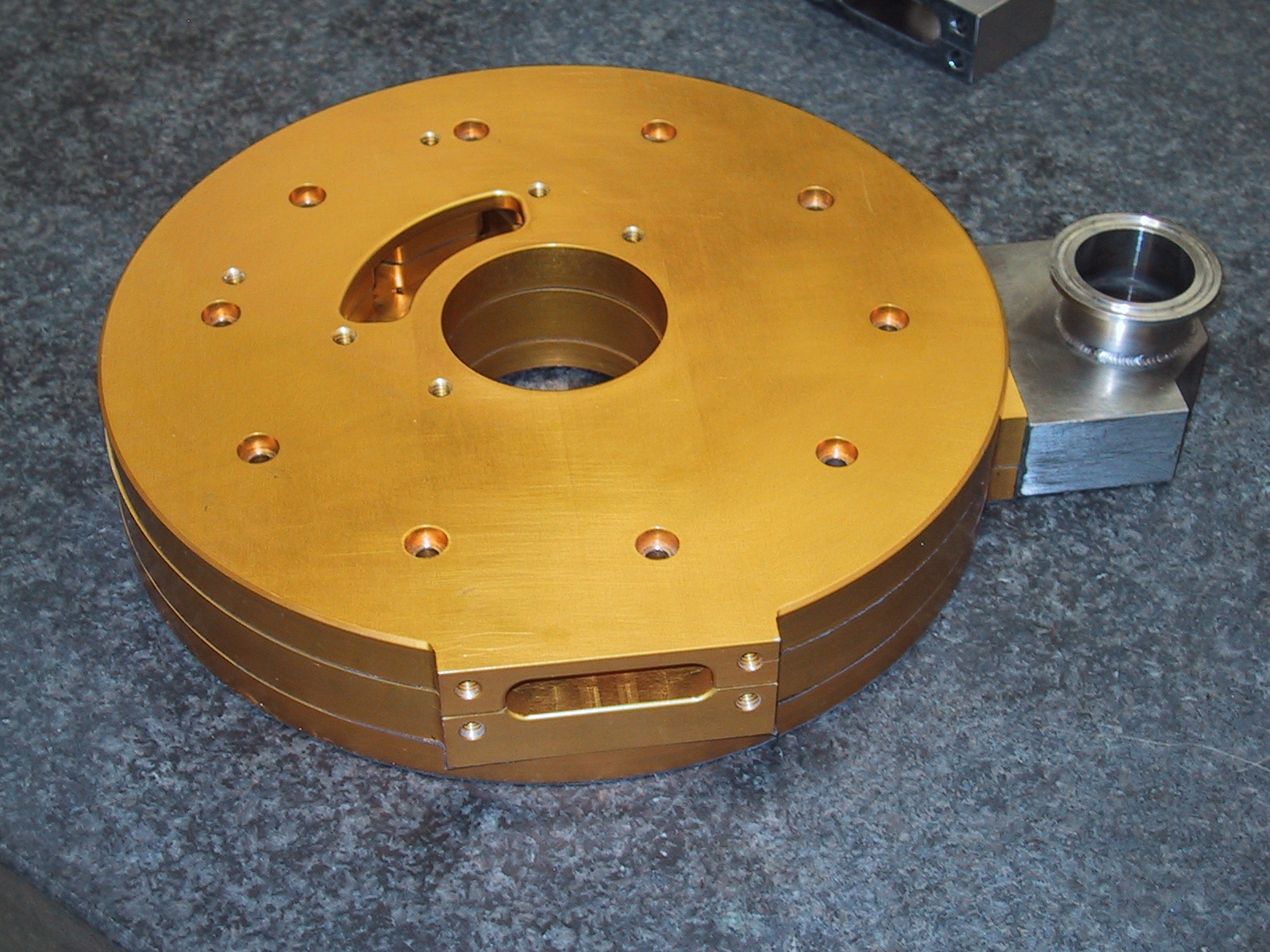
- This is the complete manifold, built up out of the three layers.
-
 Back to my Information page.