A/C circuits with resistors, inductors, and capacitors
Consider a circuit consisting of an alternating voltage source, a resistor, inductor, and capacitor in series. In general for these types of circuits we are usually given the voltage and are looking for the current as a function of time.
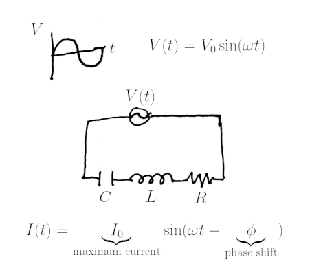
The circuit diagram above shows a typical A/C RLC circuit and the general form for the current .
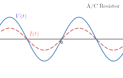
Resistor
A resistors behavior is defined by the equation . Substituting the voltage and current we get . We see that and . Since the phase shift is zero, this means that the current through a resistor is in phase with the voltage across it.
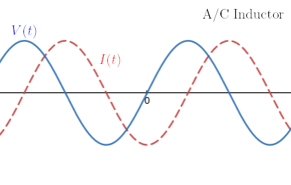
Inductor
An inductor is defined by . Substituting in the given voltage, we see that , since its derivative must be proportional to . Evaluating we find that and . Since the phase shift is positive, the current through an inductor lags the voltage across it.
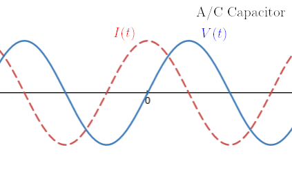
Capacitor
A capacitor is defined by . Differentiating, we find . Here the current is proportional to the derivative of voltage, so . Evaluating we find that and . This time the phase shift is negative, so the current through a capacitor leads the voltage across it.
General solution
For an A/C RLC circuit in series, we can find the general solution for current using impedance. The total impedance is:
And the total phase shift is:
Putting this together, we get:
This is a simplification. This section should be expanded.