Phasor Diagrams: Phase Shift and Amplitude in AC Circuits.
All the elements of 8.02 come together in alternating current (AC)
circuits containing resistors, capacitors, and inductors. Gauss' law
and the relation between current and charge govern the behavior of the
capacitor; Ampere's and Faraday's laws govern the behavior of the
inductor, and Ohm's law governs the behavior of the resistor. Looking
forward to the final third of the course, the lumping of a capaciter
and an inductor together produces resonating cavities and wave guides
that lead to the formulation of electromagnetic waves, which
transport energy via electric and magnetic fields.
In 8.02, the fundamental problem of determining the response of an AC
circuit to a sinusoidal voltage reduces to a methodology for adding
Asin(wt) to Bcos(wt). Figure 1 shows Asin(wt) in green, Bcos(wt) in
white, and their sum (Asin(wt)+Bcos(wt)) in red. The periods of
Asin(wt), Bcos(wt), and their sum (Asin(wt)+ Bcos(wt)) are identical, but
the amplitude and phase shift of the sum are difficult to determine by
inspecting the graph. (If you like, take 3 minutes to determine the
amplitude and phase of the red wave in terms of A and B. The
trig/algebra is developed below, but give it a try on your own first.)
This document
introduces phase vectors as a tool to determine the amplitude and
phase of the sum Asin(wt)+Bcos(wt) and shows how to use phase
vectors to solve 8.02 AC circuit problems.
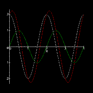
Figure 1: Asin(wt)(green),
Bcos(wt)(white), and their sum (red).
The use of phasor
diagrams is developed in four steps:
- The relationship bewteen voltage and current is determined
for the case of parallel resistors driven by an oscillating voltage
source. This example should be review for 8.02 students. The case is
"simple" because the current functions being added are all in phase.
Asin(wt) + Bsin(wt) = (A+B)sin(wt) -
The same methodology used for parallel resistors is applied to a
resistor and a capacitor in parallel with an oscillating voltage source.
-
Phasor diagrams are introduced a method for adding the currents through
the resistor and the capacitor.
-
The phasor diagram method is then extended to a circuit with
resistive, capacitative, and resistive elements, all in parallel.
Two Resistors: the simple case
The circuit portrayed in Figure 2 shows a sinusoidal voltage source in
parallel with three resistors. Given VS, R1,
and R2, the currents in all branches can be determined by
applying Ohm's Law, Kirchhoff's Loop Law, and Kirchhoff's
Node Law.
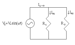
Figure 2: A sinusiodal voltage source in
parallel with two resistors.
-
Kirchhoff's Loop Law requires that the voltage across each resistor
equals the source voltage:
VR1=Vo sin(wt)
VR2=Vo sin(wt)
-
Given the voltage across the resistors, Ohm's Law defines the current
though each:
IR1=(V0/R1)sin(wt)
IR2=(V0/R2)sin(wt)
-
Kirchhoff's
node law requires that the current from source must divide between the
two resistors:
IS=IR1+IR2
IS= (R1+R2/R1R2)V0 sin(wt).
IS, IR1, and IR2 are
plotted together in Figure 3. Because IR1, and
IR2 are in phase with each other, so is their sum.
Case Closed.
The Resistor and the Capacitor: one step harder
Figure 4 shows a situation very similar to that portrayed in Figure 3,
but R2 has been replaced with a capacitor (C). The method
of solving the new puzzle is similar to the steps outlined in the
previous section. One additional bit of information is required, the
relationship between the voltage across a capacitor and the current
through it.
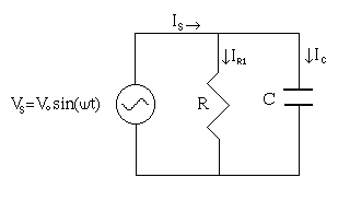
Figure 4: A sinusiodal voltage source in
parallel with two resistors.
-
Kirchhoff's Loop Law still requires that the voltage across each
resistor equals the source voltage:
VR=Vo sin(wt)
VC=Vo sin(wt)
-
Ohm's Law defines the current through the resistor:
IR=(V0/R)sin(wt)
-
To find the current in the capacitor takes a few extra steps, starting
with the definition of capacitance (C=Q/V) and the relationship
between current and charge (Q=di/dt).
Phasor Diagrams
Putting It All Together