| |
|
|
|
| |
1.Loading the AutoGrammar menu in AutoCad
1.1. Create a folder called AutoGrammar in your
directory and download the files in the Auto
Grammar folder in Archnet's MIYAGI-MIT 2001
group (under collections)
|
|
|
|
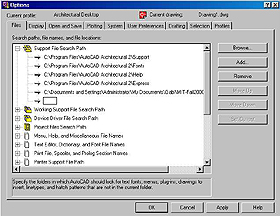
1.2. Open AutoCad and click on the Tools
menu in
the menu bar. Choose Options.
In the Options
window, make sure the Files
tab is selected.
1.3. Double click on Support
File Search Path and
then press the button Add
on the right side.
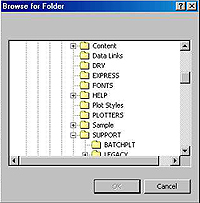
Click on the Browse button
to open the Browse for
Folder window.
|
|
|
|
1.4. In the Browse for Folder
window, navigate to
the AutoGrammar folder
under your local or remote
directory. Click on the
OK button.
1.5. Check if the new path is showing under
Support File Search Path
and click on the Apply
button on the bottom of the Options
window.
Then, click on the OK
button. Now AutoCad will be
able to find the AutoGrammar commands when
you call them from the AutoGrammar menu.
|
|
|
|
1.6. From the command promp line, type:
(This function should load the AutoGrammar
menu.)
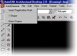
1.8. Check to see if there is a new menu group on
the left side of the menu bar on the top of your
AutoCad screen. When you click on it, the
AutoGrammar menu should
have only 3 options.
|
|
|
|
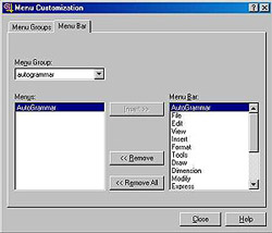
If for some reason the AutoGrammar
menu doesn't
show up or an AutoCAD menu disappears, go to
Tools/Customize Menus,
click on the Menu Bar
tab,
find the goup you are missing an option in the Menu
Group drop box, and insert the menu you want with
the Insert button.
|
|
|
|
|
|
2. Setting up AutoCad
AutoCad need to be set up first, so that we make
sure that the units are in meters and we have
enough space to draw.
|
|
|
|
|
|
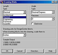
2.1. Setting up the drawing units
From the command promp line, type:
Or click on the Format menu
on the menu bar and
choose Units...
Open on the Type list
and choose Decimal. Click
on
the OK button.
|
|
|
|
|
|
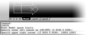
2.2. Setting up the drawing limits and the grid
From the command promp line, type:
Or click on the Format
menu on the menu bar and
choose Drawing Limits.
There will be no dialogue
box window. Look at the command prompt area
and type, followed by enter:
Specify lower left corner
[ON/OFF]<0.00,0.00>:
0,0
Specify upper right corner<12.0,9.0>:
100,100
To turn on the grid, type:
Command:
grid
Specify grid spacing[ON/OFF]<1>:
10
Or click on the Format menu
on the menu bar and
choose Drafting Settings.
Click on the Snap and Grid
tab. Check the Grid On
box on the top right side and
set the grid's X and
Y spacings
to 10.
|
|
|
|
|
|
2.3. Setting up the viewpoint
Click on the View menu
on the menu bar and
choose 3DViews and
then one of the Isometric
views (like NE Isometric).
Now you can start drafting.
|
|
|
|
| |
|
|
|
| |
Click on the Draw menu
on the menu bar and
choose Solids and
then Box. At the prompt...
Specify corner of box or [CEnter]<0,0,0>:
...click
on any point on the screen. Then, type the
following always followed by enter at the next
promts:
Specify corner or [Cube/Length]: C
Specify length: 10
You should see a box on the screen now.
|
|
|
|
|
|
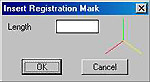
3.2. Insert Registration Mark
From the AutoGrammar
menu, choose Insert
Registration Mark.
Use this command to insert an axis tripod in the
shape to which you want to apply a transformation.
This shape can be a single object (like a line, a
point, a solid, etc.), or a group of objects.
The Insert Registration Mark
dialogue box has a field
for entering the Length,
in drawing units, for the
arms of the tripod. Enter a number big enough to
be seen, but small enough to fit inside the shapes
(e.g. 4).
|
|
|
|
It is better to apply the tripod to the corner of the
object coincident with the label chosen during the
labeling studies in 3dShaper, but avoiding
superposing it with the object's own lines, for
clarity.
Click OK and then pick
a point to insert the
egistration Mark, or just place it anywhere and
move it later to the right place with the MOVE
command (which can be typed in or found under
the Modify menu).
|
|
|
|
After inserting the Registration Mark to the shape,
copy both to the side, using the AutoCad command
COPY (which can be typed
in or found under the
Modify menu).
|
|
|
|
Apply any number of transformations to this copy
(rotation, scaling, translation, reflection). The
AutoCad commands for those transformations are
ROTATE, ROTATE3D,
SCALE, MOVE and
MIRROR, and
they can also be typed in or found under the Modify
menu. Position the copied and transformed shape
and Registration Mark in the desired spatial relation
to the original shape.
|
|
|
|
From the View menu,
choose Shade, then
Flat Shaded, edges On, and check if
your cubes
intersect each other. Go back to the wireframe
view by clicking on the View
menu again and
choosing Shade, then
2DWireframe.
|
|
|
|
|
|
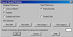
3.3. One Shape Rule
From the AutoGrammar
menu, choose One Shape.
Use this command te repeat a spatial relation
between an object with a Registration Mark and a
copy of them that has been transformed (moved,
rotated, scaled and/or reflected).
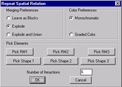
In the dialog box, check the radio buttons for
Explode and for Graded
Color. Type in 12 in the
Number of Iteractions
field.
(Please not that if you check the Leave
as Blocks
button you may not be able to run the program
again until you explode and purge all the blocks.)
Click on the Pick buttons
and click on each shape
and registration mark. Type enter
after clicking on
the shapes, which can be made of many parts.
Click on the OK button
and see how AutoGrammar
repeats the original spatial relation to each block
that is added consecutively.
|
|
|
|
To better see the result, click on the View
menu
and choose again Shade,
then Flat Shaded, edges
On. The composition should look like
the one on the
left.
Change
the color of the two original blocks if
needed, by clicking on them and choosing a
different color from the Color
list, under the menu
bar on the top of the screen.
In
the View menu,
choose 3DOrbit to examine the
composition from different viewpoints.
|
|
|
|
3.4. Two Shapes Rule
First, click below to download a drawing ready to
work on.
Open the drawing and from the AutoGrammar
menu, choose Two Shapes.
Use this command te repeat a spatial relation
between two different objects with Registration
Marks and a copy of the first one positioned to the
second according to the same spatial relation.
In the dialog box, check the radio buttons for
Explode and for Graded Color. Type in 7in the
Number of Iteractions
field.
(Please not that if you check the Leave
as Blocks
button you may not be able to run the program
again until you explode and purge all the blocks.)
Click on the Pick buttons
and click on each shape
and registration mark. Type enter
after clicking on
the shapes, which can be made of many parts.
Shape 2 and RM 2 should always be the ones in the
middle. Click on the OK
button and see how
AutoGrammar repeats the original spatial relation to
each block that is added consecutively.
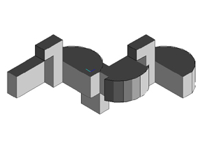
You should obtain 4 different results in each
computation.
|
|
|
|
3.5. Changing Shapes
We have finally arrived to the point at which
AutoGrammar starts showing some advantage
against other software to apply Shape Grmmars
rules. Here we will see how to make changes in the
shapes that make the chosen spatial relation
and labeling.
You won't need to make changes to shape 1; just
to shapes 2 and 3. But don't mode the Registration
Marks, or else the spatial relation will be changed.
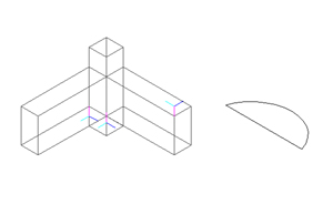
Let's start by adding a flat surface to a curved one.
First, download the following files:
There are two arrangements of shapes with
registration marks, ready for applying the AutoGrammar rules.
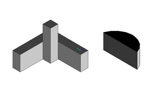
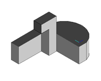
Make a closed polyline,
extrude and union it to the oblong.
Now make another on and union it to the pillar.
Apply the Two Shapes rule from the AutoGrammar
menu. Each shape now should be replaced by the new one.
|
|
|
|
| |
4.AutoCad short cuts
In AutoCad commands can be entered by 3 ways:
1)From the menu bar menus
2)From the Tool bar graphic buttons
3)By typing the command names in the command
prompt
area.
The last option can be used more efficiently
if you learn
some of AutoCad most used command's shortcuts:
| shortcut |
full command |
| 3f |
3dface |
| 3p |
3dpoly |
| a |
arc |
| aa |
area |
| bh |
bhatch |
| br |
break |
| c |
circle |
| ch |
properties |
| cha |
chamfer |
| col |
color |
| co |
copy |
| div |
divide |
| di |
dist |
| do |
donut |
| dt |
dtext |
| dv |
dview |
| e |
erase |
| ed |
ddedit |
| el |
ellipse |
| ex |
extend |
| exit |
quit |
| ext |
extrude |
| f |
fillet |
| g |
group |
| h |
bhatch |
| hi |
hide |
| i |
insert |
| l |
line |
| la |
layer |
| li |
list |
| ls |
list |
| lt |
linetype |
| lts |
ltscale |
| lw |
lweight |
| m |
move |
| me |
measure |
| mi |
mirror |
| mt |
mtext |
| o |
offset |
| os |
osnap |
| p |
pan |
| pe |
pedit |
| pl |
pline |
| pol |
polygon |
| print |
plot |
| pu |
purge |
| r |
redraw |
| re |
regen |
| rec |
rectangle |
| reg |
region |
| rev |
revolve |
| ro |
rotate |
| s |
stretch |
| sc |
scale |
| sec |
section |
| sl |
slice |
| so |
solid |
| spl |
spline |
| su |
subtract |
| t |
mtext |
| th |
thickness |
| to |
toolbar |
| tor |
torus |
| tr |
trim |
| un |
units |
| uni |
union |
| v |
view |
| vp |
ddvpoint |
| x |
explode |
| z |
zoom |
| cp |
copy |
|
|
| |
|
| |
|
| |
|
| |
|
| |
|
|
|
|