3.1 Download the self-extractable file shaper2d.exe from Archnet's MIT-MIYAGI group, under Collections and put it in a folder called shaper, so the path would be, for example:
S H A P E R 2 D - T U T O R I A L
2. Launching the Shaper2D Applet
3. Installing and running the Shaper2D Application
1. Installing Java
1.1 Download Java 2 Runtime Environment, Standard Edition (including Java Plug-in Version 1.3.0) from http://java.sun.com/j2se/1.3/jre/
1.2 Read the instructions carefully, and install Java.
2. Launching the Shaper2D Applet
2.1 Start your web browser (Netscape, Internet Explorer or Opera), and open Shaper2D from http://architecture.mit.edu/~miri/shaper2d/shaper2d.html This should launch the Shaper2D applet, and you should see the following:
2.2 If the Shaper2D applet does not launch, you will be prompted to dowload the plug-in. If you know in advance that you do not have the latest Java plug-in, it can be downloaded from http://java.sun.com/products/plugin/1.1.3/
2.3 Read the instructions carefully and install the plug-in.
2.4 The Shaper2D applet runs in exactly the same way as the application, and shares a common user interface. However, it is not possible to save designs as DXF files with the applet (for importing into CAD applications), so if this is an issue, the Shaper2D application should be installed and run instead.
3. Installing and running the Shaper2D Application
C:\shaper
3.2 Go to the shaper folder in Windows Explorer (start> Windows Explorer) and run shaper2d.exe by double clicking on it -- it will extract the source code and files to a sub-directory called shaper2d.
3.3 Go to the shaper2d directory, and run the file shaper2d.jar by double clicking on it. Alternatively, click on Start/Run in the Windows menu (bottom left of the screen), and in the Open text box type in
C:\shaper\shaper2d\shaper2d.jar
And press 'OK'This will launch the Shaper2D program. You should see the following window:
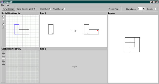
4. Introduction to the User Interface
The Shaper2D user interface is composed of a menubar, five panels and toolbars for selecting shapes. Two of the panels are grayed out by default when the program is first run. This is to emphasize the difference between using one rule and using two rules.
Whenever the user manipulates a shape in a Spatial Relationship panel, the Rule panel(s) and Design panel update in real-time. This enables the user to get an immediate response to her actions. Similarly, when we change the position of the label in the rule window, the iteration window updates simultaneously, so that we can see the effect of the rule change on our design. This is a key feature of the program, as it enables us to consider the implications of each design move instantaneously.
If we would like to start a design from scratch, we should click on the 'New Design' button which restores the default spatial relationship -- however, the program will ask us if we are sure about this, so don't be worried about losing information by accidentally pressing it!
NOTE: If we click on 'New Design' when using two rules, we will see that the 'Two Rules' Radio button is still checked after we have returned to using One Rule (the default). Don't worry about this (it's a minor bug in the program that will be fixed!) -- we should just click on the 'One Rule' radio button to remind us that we're now using one rule again.
The following is a guide to the user interface. You may find it helpful to open up your copy of Shaper2D and follow the guide for each part.
4.1 Spatial Relationship Panel: Selecting Different Shapes
4.2 Spatial Relationship Panel: Translating and Rotating Shapes
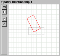
4.1 Spatial Relationship Panel: Selecting Different Shapes
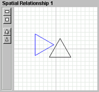
When one rule is selected, we can only use one shape, whereas when two rules is selected we can choose two different shapes. Shapes are selected by pressing the buttons on the adjacent toolbar -- each button corresponds to the shape icon displayed on it. We have a choice of four shapes: square, rectangle, equilateral triangle and isosceles triangle.
4.2 Spatial Relationship Panel: Translating and Rotating Shapes
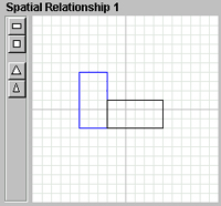
The panels on the far left are the spatial relationships -- this is where we can create and manipulate the shapes and the relationships.
Although we can translate (move) and rotate both shapes in a relationship, we are only able to resize (scale) the selected shape in that panel. This shape is highlighted in blue.
We can see the shape chosen for translating or rotating as it is highlighted in red when the cursor is passed over it.
To translate a shape, first we move the cursor to the center of the desired shape. We can see that the cursor has changed to a 'translate' cursor, indicating to us that we can now translate the shape. We then translate the shape by pressing the left mouse button and dragging the shape to where we want it, before releasing the mouse button.
To rotate a shape, we move the cursor to the center of the shape, but this time we press the right mouse button (or shift + pressing on the mouse button if we are using Mac OS). To rotate the shape, we drag the mouse around either clockwise or counter-clockwise. Once we have arrived at the desired rotation, we release the mouse button.
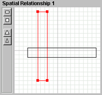
4.3 Spatial Relationship Panel: Resizing Shapes
When the cursor passes over a corner of a shape, 'handles' appear to inform us that we have the option to resize (scale) the shape. To resize, we move the cursor to the desired corner, then hold down on the left mouse button and drag the corner to where we want it, before releasing the mouse button. This is the same for each shape.
However, how we resize each shape depends on that particular shape. Resizing squares and equilateral triangles is straightforward, as the shape retains the correct proportions as it is increased and decreased in size. However, rectangles and isosceles triangles display different characteristics. We are not able to transform a rectangle into a square. This is a deliberate gesture, to emphasize to the user the particular symmetries inherent in each shape, and to reduce confusion when looking at the rules and the design. Similarly, an isosceles triangle cannot be changed into an equilateral triangle - if we try to do this, the isosceles triangle snaps back to being an isosceles triangle. We will look at the orders of symmetry, which is the reason for this restriction for shape manipulation, when we discuss the Rule panel.
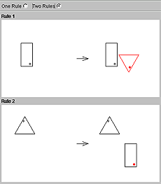
As mentioned previously, we can either use one rule or two rules when deriving our designs. With one rule, we are limited to using one shape, whereas with two rules we can use two different shapes. When the 'two rules' button is pressed, the Spatial Relationship 2 and Rule 2 panels are activated. We can then manipulate shapes in both spatial relationship panels, and modify the labels in both rule panels.
To modify a label position, we first move the cursor over the shape containing the red label, so that the shape highlights in red. We then click on the shape with the left mouse button, and we can see the label changing positions. To get an idea of the effect that this is having on the design, we should look at the Design panel, where the design changes dynamically every time the label is repositioned.
We will see that the number of positions that the label can be repositioned depends on the shape selected. This is because of the orders of symmetry inherent in the different shapes. The number of label positions we have to choose from are:
- 4 Rectangle
- 8 Square
- 6 Equilateral Triangle
- 2 Isosceles Triangle
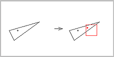
The Design panel displays our design, which is updated dynamically every time we make a change to our Spatial Relationship(s) or Rule(s).
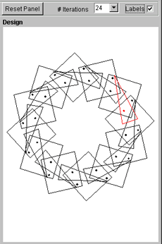
4.5.1 We can change the number of rule iterations that are displayed, by clicking on the '# Iterations' pull-down menu. The maximum number of iterations is 25.
4.5.2 We might also find it helpful to look at how the labels are positioned on the shapes during the derivation of a design. To do this, we click on the 'Labels' checkbox, and can see the labels from the previous rule iterations in black, while the current shape in the design is shown in red.
4.5.3 If a design is too big to fit into the panel, we can use the move or zoom features of the Design panel.
- Moving is done using the same principles as the Spatial Relationship panel.
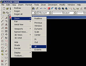
- Zooming is achieved by pressing on the right mouse button (or shift + mouse button for Mac OS) and dragging the mouse up or down, depending on whether we want to zoom in or out. We can see that the cursor changes to a 'up-down' arrow when zooming is enabled, to remind us which way to drag the cursor. We release the mouse button to set the zoom.
- If we accidentally lose the design (by moving it off the panel, or zooming in or out by too much), all we have to do is click on the 'Reset Panel' button -- this repositions the design to the origin and restores the default zoom setting.
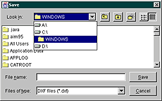
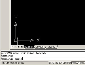
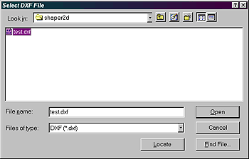
4.5.4 If we are using the Shaper2D application, we also have the option to save the design as a DXF file for importing into a CAD program such as AutoCAD. Details of importing into AutoCAD can be found below. To save a design, click on the 'Save Design as DXF' button, and save the design in the usual way (give it a name and put it into the desired directory).
5. Practice Exercises
These exercises will involve:
- selecting either One Rule or Two Rules,
- choosing the appropriate shape(s)
- translating the shape(s) to get the correct spatial relationship
- changing the label position(s) to get the correct transformation
- setting the correct number of iterations in the Design panel.
Remember, if the design goes off the panel, you can zoom and move the design to see the whole thing.
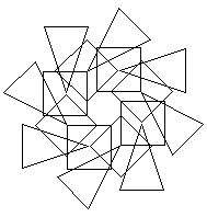
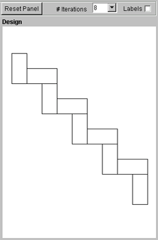
Exercise 1
Without resizing any shapes (rotating and translating is allowed), and by using one rule only, create the following designs:
a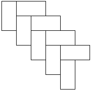 b
b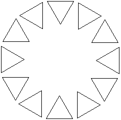 c
c 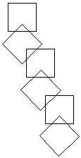
Exercise 2
Without resizing any shapes (rotating and translating is allowed), and by using two rules, create the following designs:
a 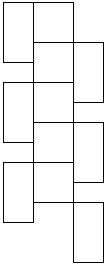 b
b 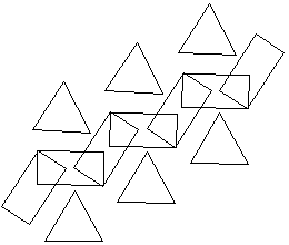 c
c