|
3 D S H A P E R - T U T O R I A L
1. Installing Java
2. Installing and running 3DShaper
3. 3Space Assistant
4. Introduction to the 3D Shaper User
Interface
5. Guided Exercises
|
|
1. Installing Java
1.1 Download Java 2 Runtime Environment, Standard
Edition (including Java Plug-in Version 1.3.0) from http://java.sun.com/j2se/1.3/jre/
1.2 Read the instructions carefully, and install
Java.
|
|
2. Installing and running 3DShaper
2.1 Download the self-extractable file 3dshaper.exe
from Archnet's MIT-MIYAGI group,
under Collections and put it in a folder called shaper, so
the path would be, for example:
2.2 Go to the shaper folder in Windows Explorer
(start> Windows Explorer) and run 3dshaper.exe by double
clicking on it -- it will extract the source code and files to a sub-directory
called 3dshaper.
2.3 Go to the 3dshaper directory, and run
the file shaper.bat by double clicking on it. This will launch
the 3D Shaper program. You should see the following window:
|
3. 3Space Assistant
3.1 To view the .iv files generated by 3DShaper download
3Space Assistant from http://www.tgs.com/pro.htm
. You will get an e-mail with an authorization code to run the program
for free for 2 weeks.
NOTE: When you request a temporary license for the program, you
should say that you need it urgently, as it can sometimes take up to
a day to be sent.
3.2 In 3Space Assistant Choose File/Open, browse
to the c:\Shaper\3dshaper folder, and open the new.iv and rule.iv (open
inventor) files. You should see the following windows:
3.3 Once the .iv files are in 3Space Assistant they
can be saved as .wrl or .bmp. The first can be imported in 3dStudio
and then exported to .dwg, whereas .bmp can be used directly in Photoshop.
You can also use the 3Space Assistant to view vrml's.
NOTE: 3DShaper always saves the models as
new.iv, so you have to open them and save them with another name before
running the program again.
|
|
4. Introduction to the 3D Shaper User Interface*
The layout is composed of five parts: the title bar,
the picture, the definition of the blocks, the transformation of Block
2, and the generation of a design.
On the top is the title - 3D Architecture Form Synthesizer.
To the right of the title, there is an About button. By clicking
on it, a dialogue box will pop up -- a brief introduction to the program
is there. Click OK to close the dialogue box.
|
|
|
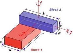
In the main window is a picture illustrating the use
of the program.
A blue block (Block 2) is attached to the top
face of a red block (Block 1), with two side faces aligned. This
shows the pre-defined, default spatial relation of an oblong and a pillar.
Width, Length, and Height (W, L, H)
define the geometric dimensions of the two blocks. The arrow directions
indicate the directions in which the width, length or height may be increased.
Because the two blocks keep their defualt spatial relation, increasing
the height of Block 2 will make it grow upwards, instead of downwards,
and intersect with Block 1. For the same reason, increasing the length
of Block 2 will make it grow longer to the right, while keeping its left
face aligned with Block 1. Block 1 follows the same rules. Increasing
its height will make it grow downwards, and increasing its length will
make it grow longer, while keeping its back face aligned with the back
face of Block 2.
|
|
|
To the right of the
picture is the definition of the two blocks. They are Width, Length,
Height, Label, and Style parameters. In Style,
there are also Graduate and UseFile parameters.
The picture does not show where the label is, since
it is showing the spatial relation, not the rules. However, the labels
can be seen later when 3Space Assistant is launched to actually look at
the rules. The default label position is 1 on both blocks, which is in
the upper right corner of the block. And since Block 2 is rotated 90 degrees,
it looks like Label 1 position is on its lower right corner. We will get
a better idea of how each label is located when we view the rules in 3Space
Assistant.
Style defines the surface property of each block.
There is a pop-up menu for each block. The default is Red Color.
By clicking on it, we can see that there are four choices for each block:
Red Color, Blue Color, Color Cube, and File. Two sub-choices are below:
Graduate and UseFile. By combining the pop-up menu with
the sub-choices, we can get many interesting surface styles for the blocks.
The default for Graduate is 0, so all the blocks in the resulting design
will be the same red or blue color. Graduate can be any positive integer
number -- the bigger the number, the slower the graduation of color. Graduate
is useful for understanding the construction of designs. Each added block
in successively lighter in tone.
|
|
|
|
Modifying the two blocks is done by transforming Block
2. Varying the dimensions of the blocks in the default spatial relation
can produce a great diversity of designs, however, the design possibilities
are still very limited. By translating and rotating Block 2, we can get
many more spatial relations between the two blocks.
The transformation of Block 2 is relative to the default
Block 2 position shown in the picture. There are two kinds of transformation:
Rotate and Move. The rotation and moving axes -- X,
Y, and Z, are shown in the picture. The direction of the
arrow shows the positive direction of the movement and rotation. Moving
and rotating in the opposite direction can be achieved by making the number
negative. Rotation is in degrees. We can rotate around any axis, however,
if we rotate around all three axis at the same time, there may be some
minor discrepancies in the final results.
Once we have input the desired blocks, spatial relation,
labels, and rules, we are ready to generate a design. The Generate
Design part is just below the Transform Block 2. It contains the Iterations
parameter, One Rule button, and Two Rules button. Also,
there is the Close button which will let us quit from the program.
The default number of iterations is 8. This means that the program will
apply the rule eight times. If Two Rules is selected, it will apply Rule
1 four times and Rule 2 four times. We can increase or decrease the number
of iterations. The number of iterations can be increased as high as 40,
but the program may crash if it goes beyond 50.
The One Rule button is different from the Two
Rules button, in that it will only run one rule, instead of two rules
alternately. For this workshop we will only be using Two Rules.
When the Two Rules button is clicked, the program
will run automatically and generate two files according to our settings.
One is called rule.iv, and the other is called new.iv. It
will take several seconds (the length of time depends on the number of
Iterations) to generate the files.
In order to view the rules (rule.iv) and the design
(new.iv), we need to launch 3Space Assistant.
|
 |
The new.iv file shows the design generated by the rules.
The program will always begin with Block 1 with its initial label on the
upper right corner. There we will put Block 2. If the label on Block 2
is 2, the next Block 1 will be put at Block 2's label 2 position. The
new Block 1 (no longer the initial Block 1) will have its defined label,
for example label 3. The next added Block 2 will be put on the label 3
position of this Block 1. Also, the new Block 2 has its label 2. The program
will continue this process recursively, until it reaches the desired number
of iterations.
|
 |
The rule.iv file shows the rules used by the design.
For the two rules, the first one is to add Block 2 to Block 1, and the
second is to add Block 1 to Block 2. Labels are shown on the added blocks
with red letters. On an oblong block there will be eight labels (1 - 8).
On a square or a pillar, there will be sixteen labels (1 - 16). On a cube
there will be forty-eight labels (1 - 48). The current label position
is shown with a red dot and a number beside it. The label position on
the block indicates where the added block will be put according to this
one.
|
|
Each time Two Rules or One Rule button is clicked,
the old new.iv will be overwritten by a new one. It is therefore important
to save our design under a new name if we decide to keep it -- this is
done by using the File/Save As function in 3Space Assistant menu bar.
As mentioned previously, files can also be saved as .wrl or .bmp. The
first can be imported in 3dStudio and then exported to .dwg, whereas .bmp
can be used directly in Photoshop. VRML files can also be viewed in 3Space
Assistant.
To rotate the design in 3Space Assistant, either move
the cursor over the drawing, press the left mouse button and drag, or
use the thumbwheels (located in the south-west corner of the window).
To zoom in and out, use the thumbwheel to the right of the display panel.
We can view our design in many different ways in 3Space
Assistant. To use a different drawing style, right click on the image
in 3Space Assistant and select 'Draw Style' from the pop-up dialogue box.
From here we have the choice of several different viewing modes, including
hidden line, wireframe, and points.
|
 
  |
|
5. Guided Exercises
Launch 3D Shaper and 3Space
Assistant. It would be helpful to open up two 3Space Assistant windows
as we will be looking at both the designs and the rules for each example.
To do this, just run 3Space Assistant twice.
After setting the block definitions and labels for
each part (or sub-part) of the following exercise, click the "Two
Rules" button, then open up rule.iv and new.iv in 3Space Assistant
to view the results.
5.1 Exercise 1
5.1.1 For the block
definitions type in the following values:
Block 1:
Width 20
Length 40
Height 10
Block 2:
Width 10
Length 40
Height 10
5.1.2 Set the labels to:
Block 1: 1
Block 2: 10
solution
5.1.3 Set the labels to:
Block 1: 1
Block 2: 9
solution
You might remember that we did these two designs
in class with Terry -- to get a better understanding of what's going
on, it might help to view the designs in hidden line or wireframe mode.
NOTE: The representation is important -- when
we view the design 'as is', the solid blocks seem to merge together
and emergent shapes can be seen.
5.2 Exercise 2
5.2.1 Keep the same block definitions as 5.1, but
this time set the X axis rotation to 17 degrees.
5.2.2 Set the labels to:
Block 1: 1
Block 2: 10
solution
5.2.3 Set the labels to:
Block 1: 1
Block 2: 9
solution
5.3 Exercise 3
5.3.1 Keep the same settings as 5.2, but change Block
2 Length to 30
5.3.2 Set the labels to:
Block 1: 1
Block 2: 9
solution
5.4 Exercise 4
5.4.1 Keep the same settings as 5.3, but change Block
2 Length to 40 and set the Z axis rotation to 23 degrees.
5.4.2 Set the labels to:
Block 1: 1
Block 2: 9
solution
NOTE: For complex designs, you might find
it helpful to increase the number of iterations to get a better idea
of what's going on.
5.5 Exercise 5
5.5.1 Keep the same settings as 5.4, but set the
Z axis move to 10.
5.5.2 Set the labels to:
Block 1: 1
Block 2: 9
solution
5.6 Exercise 6
5.6.1 Keep the same settings as 5.4, but change Block
2 Width to 1, Length to 80, and Height to 1.
5.6.2 Set the labels to:
Block 1: 1
Block 2: 9
solution
5.6.3 Set the labels to:
Block 1: 4
Block 2: 9
and the number of iterations to 20
solution
5.6.4 Set the labels to:
Block 1: 3
Block 2: 9
and the number of iterations to 8
solution
5.6.5 Set the labels to:
Block 1: 8
Block 2: 9
solution
5.6.6 Set the labels to:
Block 1: 8
Block 2: 10
solution
5.6.7 Set the labels to:
Block 1: 8
Block 2: 12
solution
5.6.8 Set the labels to:
Block 1: 8
Block 2: 15
solution
|
*Note:
The text for the Introduction to the
3D Shaper User Interface was based on chapter 4 of the 1998 MIT
SMarchS thesis 3D Architecture Form Synthesizer by Yufei
Wang, the author of 3D Shaper.
|