Axes
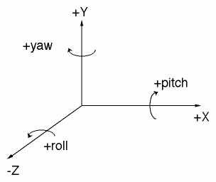
The figure above shows the three axes and the sign conventions used for both translations and rotations. The axes in VRUT are left-handed (of course). As a mnemonic, hold your left hand so that your thumb points to the right, your index finger points straight up, and your middle finger points directly away from your. Your fingers are now indicating the positive X, Y, and Z directions, respectively. The rotations about these three sames axes are referred to as yaw, pitch, and roll. The left-hand rule is used for the sign convention when rotating about these three axes. The mneumonic for this is to point your left thumb along the positive axis your want to rotate about. The rest of your fingers are now pointing in the direction of positive rotation around that axis.
The standard units used by VRUT is meters. This means that all 3D objects
built in a modeler should be built in a meters. ]
Coordinate Spaces
![]()
The typical way of conceptualizing a computer graphics pipeline is shown in the figure above. All 3D objects (such as a model created with StudioPro) start in "object space". Individual objects, or what is referred to as a layers in VRUT (not to complicate things, but a layer can really be made of multiple object all treated as a single package), are converted to a uniform "world space" coordinate system before rendering. Once in this uniform coordinate system, the transformations for the eye position and orientation are applied across all objects in the same manner. After this transformation, two additional tranformations complete the rendering process. You only need be concerned with the "Projection" transformation in order to ensure that the rendered objects are equivalent to the way real objects would appear in the real world (in terms of perspective cues, visual angles, etc.). The Perspective Transformations section below discusses these details.
Model Transformations
Model transformations refer to the mapping from object to world coordinates. To do this, VRUT allows you to define specify a sequence of transformations. There are three different kinds of transformations that you can apply: translation, rotation, and scale. In VRUT, each layer (an object or collection of objects) has its own independent sequence of transformations. Initially, all sequences are set to the identity transformation, meaning that the mapping from object to world space is one-to-one.
The order in which transformations are applied is critical, and almost always very different results will occur if applied in the wrong order. In VRUT, which follows the OpenGL convention, transformations are applied to objects in the REVERSE order in which they are specified. This means the last transformation you do to a layer should be the first one you want applied when thinking in terms of the mapping from object to world space.
As an example, say you have a model of a person facing north (nose pointed along the +Z axis) and centered about the origin. Now you want to move this object due north and rotate so that the person is looking west. Conceptually, you should first rotate the model 90 degree to the left, and then translate it away from the eye point along the +Z axis. The opposite order of transformations leads to a different result. For instance, if you first pushed the model out along the +Z axis, the rotation would have the effect of "revolving" the model arount the world origin (0,0,0); the result would be a person due east of the eye point instead of due north.
Since transformations must be applied in reverse order, the following illustrates how to achieve the result of someone standing north of the eye point but facing east:
vrut.pushlayer(vrut.WORLD, 'person.3dmf')
vrut.translate(vrut.WORLD, 1, 0,
0, 3)
vrut.rotate(vrut.WORLD, 1, vrut.YAXIS,
90)
Be careful when applying scale transformations. The scale transformation will multiply any translations that have already taken place (so it'll affect all those vrut.translate calls that are issued AFTER a vrut.scale call). So, if you move an object away from the origin by one meter and then scale everything by a factor of 2, it will actually have moved two meters. Another warning about scaling is that unequal scaling along the 3 axes will lead to non-perpendicular rotations that occur before the scale call, which can generally really make things very confusing.
The perspective translation is used to convert from world space into device space. This is the stage where 3D data gets mapped onto the 2D screen, and it is critical that the perspective transformation be exactly correct if you're interested in creating an image that's equivalent with the way objects in the real world would look.
When VRUT begins, a default perspective transformation is used. In the console mode (the small window typically used for devleopment, or what you get when you just type vrut.go() ), the vertical field-of-view (FOV) defaults to 65 deg. This is a very wide FOV to facilitate development, but beware that the perspective image is only correct for a viewing distance of 8.6 cm from the screen! Likewise, in the fullscreen modes, the vertical FOV is 75 deg, which requires a viewing distance of 18 cm for perspectively correct images! The helmet modes default to what should be close to the correct values for actual viewing (44 deg. horizontal by 33 deg. vertical).
To change the default perspective transformation, you must use the vrut.setfov() command. How to setup correct perspective transformations for both the monocular and stereoscopic are discussed below.
MONOCULAR
This procedure only applies for the CONSOLE or FULLSCREEN modes. The HMD modes are already calibrated, but this procedure can still be used to achieve special effect if desired.
There are two steps to calibrating the perspective transformation for monocular viewing:
(1) Measure the vertical FOV of the viewport. First, decide on what the viewing distance will be. The calibration will ONLY be valid at this viewing distance. Then, calculate the vertical angle subtended by the screen. To do this, measure the linear size of the vertical dimension of the viewport. In FULLSCREEN mode, it should be around 35 cm. Calculate the visual angle by dividing the vertical height by 2, and then divide by the viewing distance. The angle is 2 times the arctangent of that value.
(2) Measure the horizontal to vertical aspect ratio. To do this, measure the linear size of the horizontal dimension. The aspect ratio is the horizontal size divided by the vertical size.
Once these two quantities have been determined, then pass these values to VRE using the vrut.setfov() call. After that, the images on the monitor will be perspectively correct for that viewing distance. To verify that the projection is correct, place an object (preferably a flat square) of known size in the virtual world at distance equal to the physical viewing distance. At that simulated distance, the linear size of the object measured at the monitor should exactly equal its simulated size (in terms of width and height).
STEREOSCOPIC
There are three steps to calibrating the perspective transformation for stereoscopic viewing.
(1) and (2) are identical for MONOCULAR viewing.
(3) Measure the inter-pupilary distance of the observer.
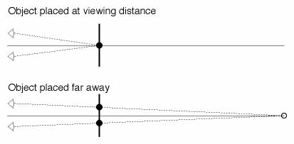
Once these three quantities have been determined, then pass the first two values to VRE using the vrut.setfov() call, and pass the third value using the vrut.setipd() call. To verify that the projection is correct, follow the steps suggested above for MONOCULAR viewing. To verify that the convergence is correct, you should see no difference between the left/right eye images on the monitor for an object rendered at the physical viewing distance. As a further test, if the object is moved very far away (+Z direction), the left/right eye images on the monitor should separate by an amount exactly equal to the inter-pupilary distance. This is illustrated in the figure below. The plan view shows the observer's eyes to the left, the monitor represented by the thick vertical line, and the left/right eye monitor images by the filled circles. When the object is placed far away, the monitor images diverge to create the virtual image far away, as represented by the open circle.